Description
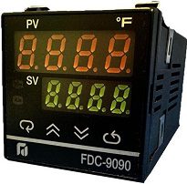
Future Design Controls
*Special Order Notes
The last digit (Special Order selection) is typically left blank (factory default)
- factory default hardware is for T/C (type J) input
- hardware defines input type: T/C and RTD input
- input type may be changed between T/C and RTD by opening or closing a solder bridge (consult factory)
Factory default software configuration remains as Type J T/C F and must be changed to appropriate RTD input and/or C.
***Standard lead-time is 2-3 weeks***
Additional information
| Weight | 3 lbs |
|---|---|
| Dimensions | 4 × 4 × 2 in |
| Power Input | 4 – 90-264Vac, 5 – 20-32Vac/Vdc, 9 – Special Order |
| Signal Input | 5 – Configurable, 9 – Special Order See Order Code 9 to specify hardware configuration for RTD input |
| Range Code | 1 – Configurable, 9 – Other |
| Control Mode | 3 – PID/On-Off |
| Output 1 Option - FDC | 0 – None, 1 – Relay form C (SPDT) 3A/240VAC, 2 – SSR Drive 24VDC @20mA, 3 – 4-20mA linear, 4 – 0-20mA linear, 5 – 0-10VDC linear, 9 – Other |
| Output 2 Option - FDC | 0 – None |
| Alarm Output | 0 – None, 1 – Relay 2A/240VAC, 9 – Special Order – Contact SPI |
| Communications | 0 – None |
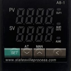
| Special Order* | Blank – Factory Default, TC – T/C Input (type J) / deg C, RF – RTD input / deg F, RK – RTD input / deg C, BF – Blank Face gold outline T/C input (type J) deg F, BC – Blank Face gold outlined T/C input (type J) / deg C, RB – Blank Face gold outlined RTD input / deg F, RC – Blank Face gold outlined RTD input / deg C |


Reviews
There are no reviews yet.